


After collecting steam traction engine steam gauges for many years, I begun to see interesting developments in their evolution. It was these gauge developments that started to peak my curiosity as to the technological developments of the steam engines they were used on.
Steam gauge history
The most common company name I’ve seen on traction or farm engine steam gauges is the J.I. Case Threshing Machine Co., and probably the most common maker of these gauges was the Ashcroft Mfg. Co. who held the U.S. patent to the Bourdon gauge dated Aug. 3, 1852. Both companies had their start in the mid-1800s, Case in 1842 and Ashcroft later in 1851. But it wasn’t until 1869 that Case built its first portable steam engine. The first of over 36,000 may be the reason we have seen so many surviving Case gauges.
In the beginning, there wasn’t much for the traction engine makers to choose from in the way of steam gauges. When Case built its first engine (just a portable engine, not a traction engine), the choice was between a diaphragm gauge and a Bourdon gauge. Most diaphragm gauges of the time consisted of a pressure chamber with a corrugated disc of thin metal that would deflect under pressure. The deflection was transmitted to a pointer on the dial through various linkages. On the other hand, the Bourdon gauge operated with a horseshoe shaped tube that would attempt to straighten under pressure. The movement of the Bourdon tube was also transmitted to a pointer on the dial of the gauge through linkages. By 1869, when Case needed to order gauges for its engines, the Bourdon gauge had already begun to surpass the popularity of the diaphragm gauge.
For the traction engine maker, I would suspect the deciding factor was the invention of the T.W. Lane improvement on the Bourdon gauge patented on Feb. 22, 1859. In its 1876 catalog, American marketed its Lane gauge as one that “removes all objections to the original gauge for locomotives, portable engines, and other moving machinery.”
In 1869, Case was probably aware of the superior improvement that the T.W. Lane patent offered over the original Ashcroft patent. Because the addition of the user company name did not become common until the mid- to late-1870s, the early Case gauges most likely did not have the J.I. Case name on their dials.
Photos 1 and 1A (view all photos in the Image Gallery) are an early example of a small 5-inch dial, American Steam Gauge Co. gauge with the 1852 Ashcroft patent and the 1859 T.W. Lane patent. It is very likely that a gauge similar to this would have been used on the early Case engines.
From several Case histories I’ve seen, it appears that seven years after the development of the first Case steam engine, the first Case “traction engine” was produced in 1876.
Photos 2 and 2A, J.I. Case gauge has a pressure range of 0-180 pounds. Therefore, the working pressure for the engine should be around 90 pounds. This Ashcroft trademark was used from 1878 to 1897.
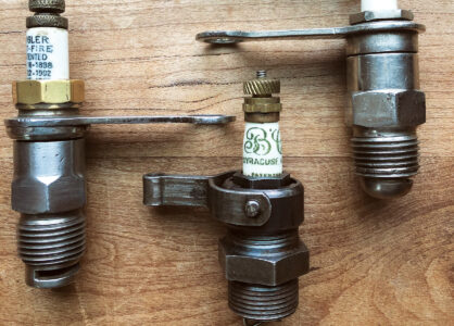
Working pressure for an engine using a 200-pound gauge would be around 100 pounds. An Ashcroft trademark (Photos 3 and 3A) saw use from 1898 until 1907. It also sports the 1884 Ashcroft auxiliary spring patent that was used extensively on traction engine gauges.
Photos 4 and 4A are an unusual Ashcroft trademark used between 1902 and 1907. A 250-pound J.I. Case threshing machine gauge with an engine operating pressure around 125 pounds.
Photos 5 and 5A are the same gauge as the 1902 but with the 1907 Ashcroft trademark. I have seen many of the 1902 J.I. Case gauges, but only one of these. It must have been the transition where J.I. Case was still using the 250-pound gauge but Ashcroft started using the 1907 trademark.
Ashcroft used a trademark (Photos 6 and 6A) from 1907 until the merger in 1929 with the American Steam Gauge & Valve Mfg. Co. We don’t see any more increases in the maximum pressure of 300 pounds for Case gauges. The Case histories state that the last Case steam engine rolled off the production line in 1924.
During my 16 years of pursuing gauges, I found it frustrating that there was so little information on steam gauges. I had to compile the histories of the each gauge maker company from old catalogs and obituaries of their founders while working closely with several historical societies.
It took me 12 years to complete a collector’s guide for steam gauge enthusiasts. In 2003, I made the guide with its large chapters on railroad, traction engine and fire engine gauges, available to other collectors. It is called The Antique American Steam Gauge, a Collector’s Guide, and is available from Astragal Press and through Farm Collector Books.
Steam gauge museum
After putting the finishing touches on the guide, I needed a new project. We don’t often have the opportunity to view these original gauges because they are tied up in private collections. I wanted to at least make my collection more accessible to those who wished to view it by housing it in a kind of steam gauge museum, if you will. The perfect venue for such a collection would be the original setting for a steam gauge.
A 19th century steam water works in the New England countryside sprang to mind. Unfortunately, this was difficult to find in northern Utah. The next best thing would be a railroad building or piece of rolling stock like an old palace car. Again, these choices proved difficult to locate, but what I did find was an old railroad caboose to restore. I had considered a caboose from the period of the collection, but wood cabooses have not held up well through the years. The wood cabooses I could locate would have had to be torn down and rebuilt board by board. My wife wasn’t too excited about a railroad caboose in the backyard, but the thought of getting all those gauges out of the house appealed to her even more.
Then I found the perfect caboose for the job. When I saw her laying there at an Ogden, Utah, railcar repair yard, she wasn’t much to look at. At only 37 years old, she was originally numbered CB&Q13648 (Chicago, Burlington and Quincy). After a merger and rebuild in 1991 she was renumbered BN12595 (Burlington Northern). The windows had been welded over with steel plates when the Federal Railroad Administration required “laminated safety-type glass” installed on or before June 1, 1975, and her roof walks removed. The paint was extremely oxidized after enduring a few long hot summers languishing in the Utah sun. In addition, workers had cannibalized her for parts. After all that, vagrants had started a wood fire in her kerosene stove causing severe damage to the paneling around the stove and heat/smoke damage to the rest of the caboose. It would be a job, but something that was doable, rather than the complete rebuild I could expect with the local wood cabooses.
I’d heard horror stories about moving a caboose. An extended cupola caboose sticks up pretty high. After consulting with a local heavy haul and rigging company, I learned that if we could keep it under 17 feet 6 inches, we could avoid the police escort that would double the move charge for the meager 55 miles of travel. I saw a picture on the Internet where they had cut the cupola off a Burlington Northern caboose but I wanted no part of that. The movers were finally able to locate an extremely low low-boy trailer that they were able to lower to just a few inches above the road and get it under the high load limit. That solved, it was now time to locate a crane capable of lifting/maneuvering 45,000 pounds, but actually two would be needed, one on each end of the move. And then there were the building codes in our community. Fortunately, we live in a small farming community where the standard building lots of 1-1/4 acres often accommodate several out buildings and in this case, a railroad caboose.
Location and placement decisions were also looming on the horizon. I wanted my railroad caboose to be as authentic as possible and yet maintain its principle purpose as a steam gauge museum. The current trucks (wheel sets) weren’t original, but rather box car trucks. Additionally, the wheels and rails would lift the step entrance almost 2 feet higher. I needed to maintain easy access for visitors so I opted for the “unthinkable” and placed the bolsters, where the trucks used to sit, directly on concrete footings. This allowed the steps to rest at ground level.
The 3-foot deep concrete footings were poured. I embedded loops of 1-inch rebar into the concrete to attach to the steel beams under the caboose. A gravel parking area was built and prepared for the crane to sit on. The purchase price was paid and the day of the move came. For once, I was happy that Utah was in a drought. I had nightmares about the trailer or crane sinking to its axles in mud. I was pleasantly shocked that the stabilizers of the crane sank only an inch or two.
The pick off the rail and load onto the trailer went surprisingly well. But like any project of this magnitude, there always has to be a catch. My catch was that I was unfamiliar with a little known Utah law that applied to heavy haul companies preventing them from being on the road during rush hour.
It was 3 p.m. in the afternoon by the time the caboose was loaded so it had to sit until the next morning throwing off my crane schedules. I had not arranged for a crane the following day. Fortunately, the picking crane company was willing to drive the 55 miles, at 30 mph, to my location for $125 per hour, including drive time, both ways.
It was thrilling seeing the caboose coming across the river into Newton, Utah. There was a pilot car in the lead with a tall pole attached to the fender. The pole was extended to the same height as the load so as to identify wires that had to be manually lifted out of the way of the caboose.
Carefully, the crane operator swung the caboose off the truck and sat it on the concrete footings. Now the hard work began.
It would take almost a year to restore the caboose. A very kind mechanical engineer at BNSF (Burlington Northern Santa Fe) was extremely helpful in the restoration. He was able to copy to a computer disk many of the original blue prints and several original pictures of the caboose.
I had to run electrical lines and restore the exterior. I used polishing compound to remove the oxidation and a clear coat epoxy to seal the old exterior paint. I also had to freshen up the logos and numbering with white paint. I was able to fabricate several of the missing pieces including the grab irons and replaced the roof walks. I was actually able to find an original firecracker antenna and marker light on the Internet.
After the caboose was complete, I installed the display cases for the steam gauge collection. Railroad gauge displays include locomotive boiler gauges, brake gauges (locomotive and railcar), heating and lighting gauges, feed water and stoker gauges. Traction engine and early fire engine gauges are also a favorite of mine.
If you’re planning a trip to the area, please write for an appointment. ST
Contact the Antique American Steam Gauge Museum at P.O. Box 152, 161 S. 100 E., Newton, UT 84327.
The Antique American Steam Gauge, a Collector’s Guide, printed by Astragal Press, is available through Farm Collector Books.


